Panel data
Sheet sizes, thickness and surface-treatment limits from the current product reference. Series-specific imagery and descriptions remain on the Materials pages.
Sheet ranges and surface treatment
| Series | Sheet size | Thickness | Surface treatment |
|---|---|---|---|
| Resin light-diffusing | 1200 × 2400 / 1200 × 3000 mm | 3-25 mm; 50 mm produced | Confirm the required finish with the sample |
| Crystal thin sheet | 1200 × 2400 / 1200 × 3000 mm; 1180 × 2400 / 1180 × 2980 mm at 30-40 mm | 6-100 mm | Manual and fine matte; super-fine matte is not available |
| Crystal through-body | 1200 × 2400 / 1500 × 3000 / 2000 × 3000 mm | 3-100 mm | Confirm finish against the approved sample |
| High transparency (B) | 1200 × 2400 / 1200 × 3000 mm | 3-12 mm | Mechanical edge polishing; fine and super-fine matte |
| Remodelled resin | 1200 × 2400 / 1200 × 3000 mm | 12 mm and above | All standard surface treatments; recommend medium matte face with fine or super-fine matte back |
| High transparency in remodelled | 1200 × 2400 / 1200 × 3000 mm | 12 mm and above | All standard surface treatments |
| Washi paper | 1200 × 2400 / 1200 × 3000 mm | 6 mm and above | All standard surface treatments |
| Diamond plate | 1200 × 2400 / 1500 × 3000 / 2000 × 3000 mm | 20 / 22 mm | Faceted surface; confirm edge and grain direction |
| Light-transmitting stone | 1200 × 2400 / 1200 × 3000 mm | 6-20 mm; normally 9.5 / 10 mm | Confirm finish with the approved sample |
Thickness planning
These ranges are a starting point for discussion. Final thickness depends on span, support, lighting, edge treatment and the requirements of the local installer or engineer.
| Application | Condition | Suggested thickness | Note |
|---|---|---|---|
| Background wall | Direct fixing | 3-20 mm | Confirm substrate and fixing method |
| Backlit | 10, 12, 15 or 20 mm | Large areas require additional fixing | |
| Curved background | 10, 12, 15 or 20 mm | Confirm radius and panel size | |
| Partition | 15 or 20 mm | Confirm frame and edge support | |
| Partition up to 1200 mm high | 12, 15 or 20 mm | Confirm support at the base and edges | |
| Cabinet | Shelf or upright spacing up to 400 mm | 10, 12 or 15 mm | Confirm fixing and load |
| Spacing over 400 mm | 12 or 15 mm | Confirm support and load | |
| Countertop | General | 30 mm | Thicker sections are available by review |
| With continuous support | 15, 20 or 30 mm | Appearance and edge detail determine choice | |
| Bar counter | Assembled counter | 12, 15 or 20 mm | Confirm internal support |
Design & fabrication
Use the tool loss as part of layout planning. It is cutting loss at the blade or cutter and is not an additional edge-finishing allowance.
Fabrication methods
Edge profiling, splicing, engraving, drilling and hot bending completed in our own workshop.
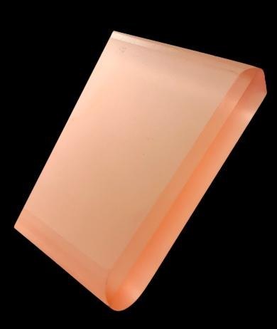
Chamfer
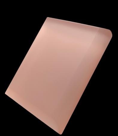
R corner
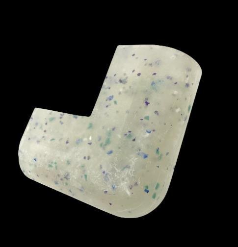
Large four-sided R
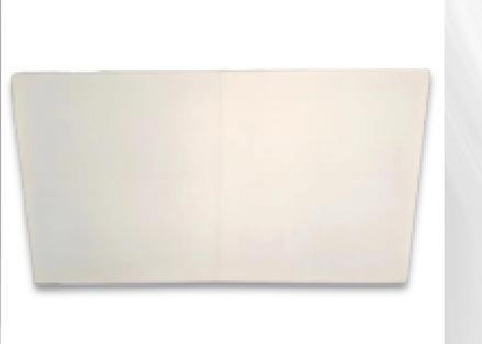
Butt splice
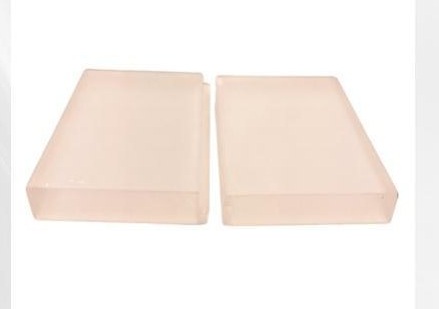
Tongue-and-groove splice
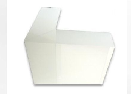
45° splice
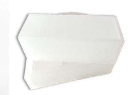
Pentahedron splice
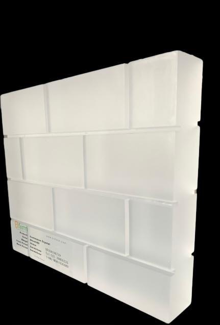
Slotted wall tile
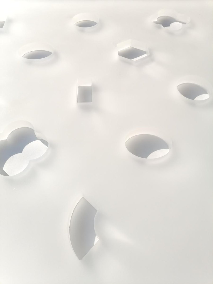
Drilling
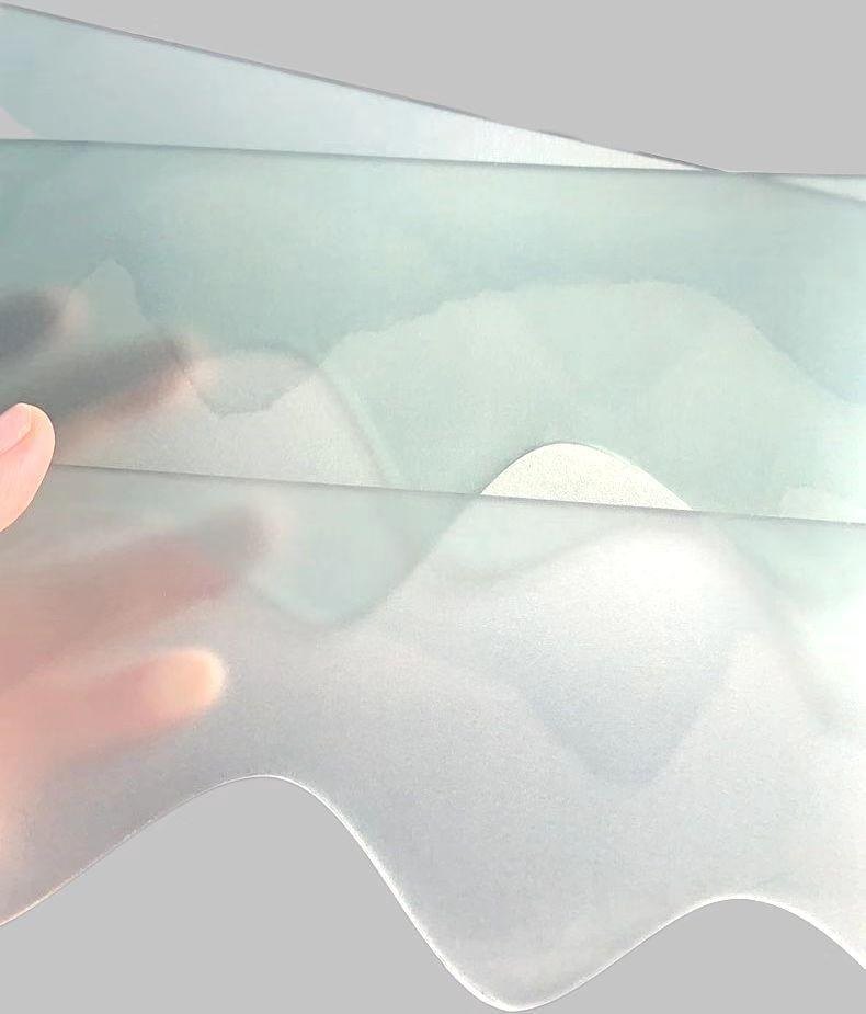
Curve

Relief carving

Custom logo
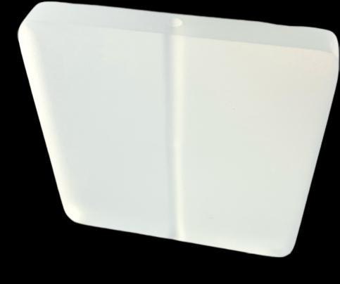
Custom cut-out
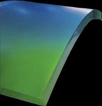
Single curved surface
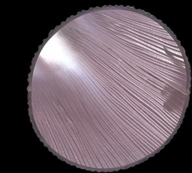
Round

Twist

Vacuum forming

Double curved surface
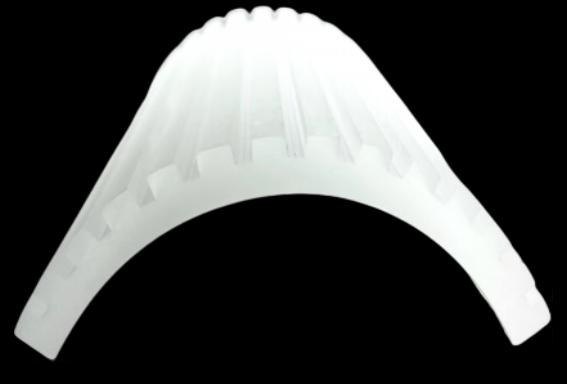
Semicircle
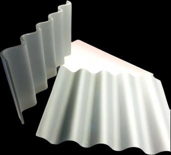
Multi-surface
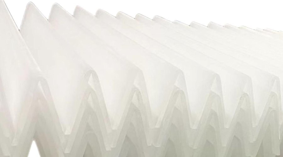
Folded edge
Cutting and tool loss
| Panel thickness | Blade thickness | Tool loss | Use |
|---|---|---|---|
| 3-6 mm | 2 / 2.6 mm | 4 / 5.2 mm | Rectangular cuts |
| 6-10 mm | 2 / 2.6 mm | 4 / 5.2 mm | |
| 10-15 mm | 3 mm | 6 mm | Panel-saw cutting |
| Above 15 mm | CNC | See CNC table | CNC processing applies above 15 mm |
| Panel thickness | Tool diameter | Tool loss | Use |
|---|---|---|---|
| 3-6 mm | 3.17 / 4 mm | 10 mm | High precision; complex shapes |
| 6-10 mm | 4 mm | 10 mm | |
| 10-15 mm | 6 mm | 10 mm | |
| 15-50 mm | 8-10 mm | 20 mm |
| Laser cutting | Laser parameters | Tool loss | Use |
|---|---|---|---|
| 3-6 mm | TO CONFIRM | 10 mm | Tool loss follows the CNC table |
| 6-10 mm | TO CONFIRM | 10 mm | |
| 10-15 mm | TO CONFIRM | 10 mm | |
| Above 15 mm | TO CONFIRM | 20 mm |
Hot bending
Recommended bend radius: Rrec ≥ panel thickness (T) × 3.5-5. Allow 50 mm on each edge. The finished sizes below already include the loss.
| Material | Maximum finished size | Panel thickness | Minimum radius | Textured allowance |
|---|---|---|---|---|
| Material A | 1100 × 2300 / 1100 × 2900 mm | Below 5 mm | 50 mm | 100 mm |
| 5-10 mm | 60 mm | 120 mm | ||
| 10-20 mm | 100 mm | 200 mm | ||
| 30 mm | 150 mm | 300 mm | ||
| Above 30 mm | Determined by actual process conditions | |||
| High-transparency B | 1100 × 2300 / 1100 × 2900 mm | Below 5 mm | 50 mm | 100 mm |
| 5-10 mm | 60 mm | 120 mm | ||
| 10-20 mm | 100 mm | 200 mm | ||
| 30 mm | 150 mm | 300 mm | ||
| Above 30 mm | Determined by actual process conditions | |||
| Resin panel | 1100 × 2300 / 1100 × 2900 mm | Below 5 mm | 50 mm | 100 mm |
| 5-10 mm | 60 mm | 120 mm | ||
| 10-20 mm | 100 mm | 200 mm | ||
| 30 mm | 150 mm | 300 mm | ||
| Above 30 mm | Determined by actual process conditions | |||
Splicing, joints and lighting
Custom pattern allowance: leave 25 mm around the pattern. Pattern cutting must retain an overlap area.
Right-angle joints
| 3-12 mm | Laser cutting can avoid an internal R corner |
| 12-15 mm | Internal R2; external corner unaffected |
| Above 15 mm | Internal R3; external corner unaffected |
Backlighting reference
| Tube pitch | 150-180 mm |
| Tube to panel | 120-150 mm |
| LED strip to panel | 100-120 mm |
| Minimum strip clearance | 80 mm |
Installation & ordering
The local installer must verify the substrate, adhesive compatibility, site conditions and applicable building requirements.
Adhesive installation
- 01Check the substrate
The timber substrate must be flat, clean and free from loose dust. Uneven backing can create a visible step at a joint.
- 02Keep panels flat
Store panels on a flat surface. Do not lean them against a wall or stand them on edge.
- 03Prepare the panel back
Remove the protective film, clean the back and apply foam double-sided tape with structural adhesive at the approved positions.
- 04Prepare the seam
Where two panels meet, profile the meeting edge to R3 when required by the panel thickness and approved detail.
- 05Position and press
Place the panel, then press or gently tap it into even contact with a rubber mallet. Check alignment before the adhesive sets.
Drawing checklist
Drawings
- Confirmed PDF set
- DWG plan, elevations and detail sections
- Rendered view
- 3D model for complex geometry
Panel scope
- Panel family and finish
- Required thickness and sheet size
- Seam direction and joint details
- Edge, cut-out and bending requirements
Delivery
- Destination and port
- Packing preference
- Site access and lifting limits
- Required delivery sequence
Inquiry workflow
Send the idea with a rendering, reference image or drawing.
We propose the panel, colour and construction, then prepare samples.
Approve the physical sample and finalise the panel schedule.
Production, packing, delivery and after-sales coordination.